

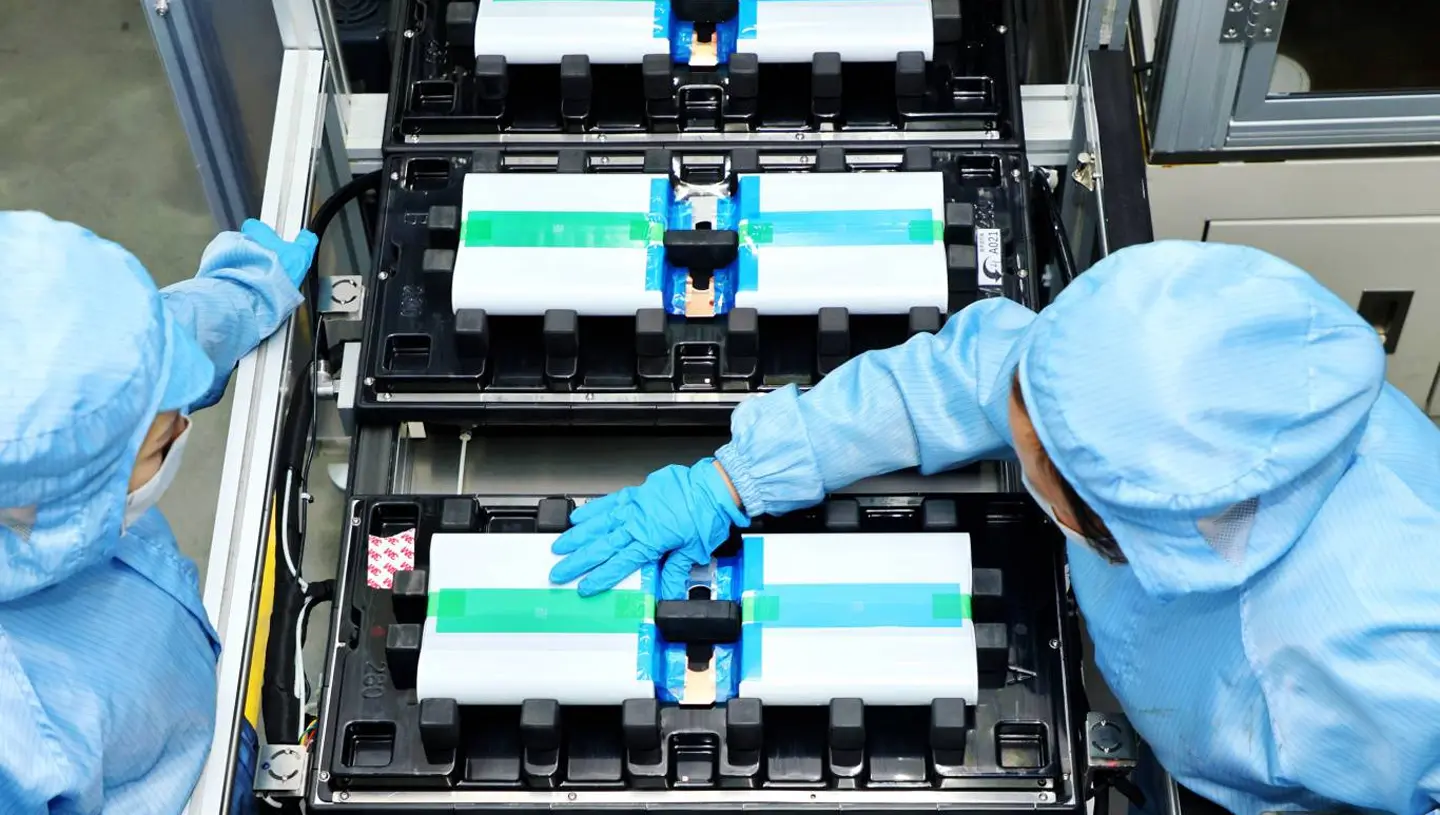
Prismatic cell production presents a fundamental process decision: whether to build the electrode assembly by winding the electrode stack into a flattened jelly roll or by stacking individual electrode sheets. The choice affects nearly every downstream parameter, including energy density, cycle life, rate capability, manufacturing cost, and equipment layout. Prismatic cells are the dominant format for electric vehicle and grid-scale storage applications because their rectangular form packs efficiently and their aluminum shell supports large cell capacities, commonly 60 to 100 Ah in automotive designs and 280 to 320 Ah or more in stationary storage.
The two assembly routes converge on the same product family but diverge sharply in equipment and physics. Winding is fast and mature but imposes geometric stress at the flattened corners. Stacking is more flexible and delivers higher performance but historically costs more and runs slower. This article compares the two routes across the metrics that matter for prismatic cell production investment decisions.
Winding in Prismatic Cell Production: Advantages, Limitations, and Equipment
How Winding Works
In winding-based prismatic cell production, the anode, separator, and cathode webs are wound around a mandrel, typically an oval or flat mandrel that shapes the final jelly roll. The wound roll is inserted into the prismatic case, pressed, and connected to the terminals. The process is continuous and fast: modern winding machines can complete a jelly roll in a few seconds, which makes winding the highest-throughput assembly route in prismatic cell production.
The equipment chain is well established. Slitting machines cut the coated electrodes to width, winding machines tension and align the three webs, and hot pressing compresses the finished roll into the case profile. Automatic web alignment, tension control, and online inspection systems have matured over more than two decades of cylindrical and prismatic production. Winding machine suppliers offer models covering the common prismatic sizes, and the process window is well understood.
Limitations of Winding
The geometry of a flattened jelly roll is the source of its limitations. The semicircular end regions carry high curvature, which concentrates mechanical stress in the electrodes at the fold. During cycling, the electrodes expand and contract; the curved regions cannot accommodate this expansion as uniformly as flat layers, which can cause delamination, lithium plating, and capacity fade over thousands of cycles. The stress is more severe for thicker electrodes and larger cells, so winding is less attractive for very large prismatic formats.
Heat dissipation is a second constraint. The wound roll has a long thermal path from the interior to the case wall, and the dense central region accumulates heat during high-rate charge and discharge. This limits rate capability compared with stacked cells of equivalent capacity. Tab design also affects performance: wound prismatic cells often use a single tab or a small number of tabs, which increases the current path length and internal resistance.
Winding still suits a wide range of products in prismatic cell production. Small and medium prismatic cells in the 20 to 80 Ah range are commonly wound, especially where throughput and equipment cost matter more than the last few percentage points of energy density.
Stacking in Prismatic Cell Production: Z-Stacking, Multi-Layer, and Emerging Methods
Z-Stacking
Z-stacking uses a continuous separator sheet folded in a zigzag pattern. Cut electrode sheets are inserted alternately between the separator folds, and the separator is cut at the end of each cell stack. Because the separator remains continuous through the folds, the process achieves high placement speed while retaining the flat-layer geometry of a stacked cell. Modern Z-stacking equipment places electrode sheets at cycle times below one second per layer, which has narrowed the throughput gap with winding and expanded the role of stacking in prismatic cell production.
Multi-Layer Stacking
Multi-layer stacking places pre-cut electrode sheets onto the separator in a layered sequence using vacuum suction or electrostatic gripping. The process offers precise alignment and is compatible with a wide range of electrode lengths and thicknesses. Throughput depends on the number of parallel placement heads and the handling cycle time; multi-head machines can approach winding-level output on a per-line basis, though at higher equipment cost and larger footprint.
Emerging Methods
Equipment suppliers are developing roll-to-sheet integration, where electrodes are cut from the coated web and stacked in a continuous process, eliminating intermediate sheet handling. Laser cutting, improved suction grippers, and vision-guided placement reduce cycle time and improve alignment accuracy. These developments matter for prismatic cell production because they target the two historical weaknesses of stacking: speed and cost.
Stacked cells gain performance from their structure. The flat layers eliminate corner curvature stress, allowing the electrodes to expand and contract evenly during cycling. Multiple tabs or full-length tab designs shorten the current path, reduce internal resistance, and improve heat transfer to the case. These effects become more pronounced as cell size grows, which is why stacking is the dominant route for large prismatic cells and long cells in the blade format.
Head-to-Head Comparison for Prismatic Cell Production
Energy Density
In prismatic cell production, stacking generally achieves higher volumetric energy density than winding in the same case. The flat layers use the rectangular case corners more completely, while the curved ends of a jelly roll leave unused volume. Industry comparisons typically attribute a 3 to 8 percent volumetric energy density advantage to stacking for equivalent electrode chemistry and case size. The advantage widens for large cells, where corner losses represent a smaller fraction of a wound roll but the curvature stress limits how tightly the roll can be compressed.
Cycle Life
Stacked cells tend to outperform wound cells over long cycling because flat electrodes experience lower mechanical stress during volume change. The difference becomes visible after several thousand cycles in applications such as grid storage, where cells must last 6,000 to 12,000 cycles. Independent test data published by research institutes such as Fraunhofer ISI shows that mechanical degradation in the curved regions of wound electrodes is a recognized failure mode, and flat-layer designs reduce this mechanism.
Rate Capability
Rate capability favors stacking for the same reasons: shorter current paths, more uniform current distribution, and better heat dissipation. A stacked cell with multiple tabs or a full tab design can sustain higher continuous discharge rates and faster charging than a wound cell of equal capacity. For power-oriented applications, the difference is material; for energy-oriented applications, it may be negligible.
Cost
Winding retains a clear cost advantage in equipment. Winding machines are simpler, faster, and less expensive than stacking machines of equivalent throughput, and the mature supply base keeps prices competitive. Stacking equipment costs more per line and requires more floor space, more precise cutting and alignment, and more material handling. Labor and maintenance are also higher because stacking involves more moving parts and more frequent tooling changes between formats.
The cost balance shifts when cell size grows. For large prismatic cells, the performance and yield benefits of stacking can offset the equipment premium, especially where energy density and cycle life are priced into the product.
Hybrid Approaches and Equipment Considerations
Some prismatic cell production lines combine winding and stacking. A common configuration uses winding for high-volume smaller cells and stacking for large or high-performance cells on the same site, sharing the upstream electrode process and downstream assembly, filling, and formation equipment. This gives the plant flexibility across product segments without duplicating the coating and drying infrastructure.
Equipment selection depends on the electrode, not only the format. Thick electrodes with high areal capacity are more difficult to wind without cracking, which favors stacking. Electrodes with high binder content or fragile coatings may also require the gentler handling of a stacking process. The electrode manufacturing side, including coating uniformity and calendering, must be matched to the chosen assembly route; see the guide to battery quality control for the coating and alignment measurements that support both routes.
Production planning must also account for changeover. Winding machines require mandrel and tooling changes between cell sizes. Stacking machines require cutting die changes, gripper changes, and alignment recalibration. A line that must switch frequently between cell formats should evaluate changeover time as part of the route decision, not only the steady-state cycle time.
Which Process for Which Application?
Application requirements are the clearest guide for prismatic cell production route selection.
For small and medium prismatic cells in the 20 to 80 Ah range used in two-wheelers, light electric vehicles, and entry-level storage, winding is usually the right choice. The performance penalty of the wound geometry is small at this scale, while the throughput and equipment cost advantages are decisive.
For automotive cells in the 100 Ah class and above, stacking is increasingly standard. Large wound rolls suffer more corner stress and internal temperature rise, and the energy density and cycle life losses grow with cell size. Most new automotive prismatic platforms use stacked electrodes, including long blade-format cells.
Reference cases illustrate the trend. The BYD Blade battery uses a long, thin LFP cell built with stacked electrodes and a cell-to-pack architecture that improves pack-level energy density by removing module structures. The CATL Qilin battery applies cell-to-pack integration to large prismatic cells with liquid cooling, and its large-format cells rely on flat stacked electrodes. Both products demonstrate that stacking supports the cell sizes and lifetime requirements of modern electric vehicles and stationary storage.
For grid storage cells of 280 Ah and above, stacking is effectively mandatory. The cycle life requirements, the large electrode area, and the safety margins of these products are difficult to achieve with a wound roll, and the flat electrode stack also simplifies thermal management in high-capacity modules.
Conclusion: The Trend Toward Stacking in Prismatic Cell Production
Prismatic cell production is shifting from winding toward stacking as cells grow larger and cycle life requirements tighten. Winding remains a strong process for smaller cells, where its speed and cost advantages dominate. Stacking has become the standard for large automotive and storage cells, where flat-layer geometry delivers higher energy density, longer cycle life, and better rate capability.
The historical trade-off was speed: winding was faster. Z-stacking, multi-head placement, and roll-to-sheet integration have narrowed that gap, and the equipment cost premium of stacking continues to fall as volumes grow. For line planners, the decision is no longer one of performance versus cost alone; it is a question of matching the assembly route to the cell size, chemistry, electrode design, and application lifetime.
TOBGROUP configures prismatic cell production lines with winding or stacking assembly according to product requirements, including blade-format and large-capacity cells. Explore battery production line solutions or review completed production line projects for prismatic line configurations across automotive and stationary storage applications.


