

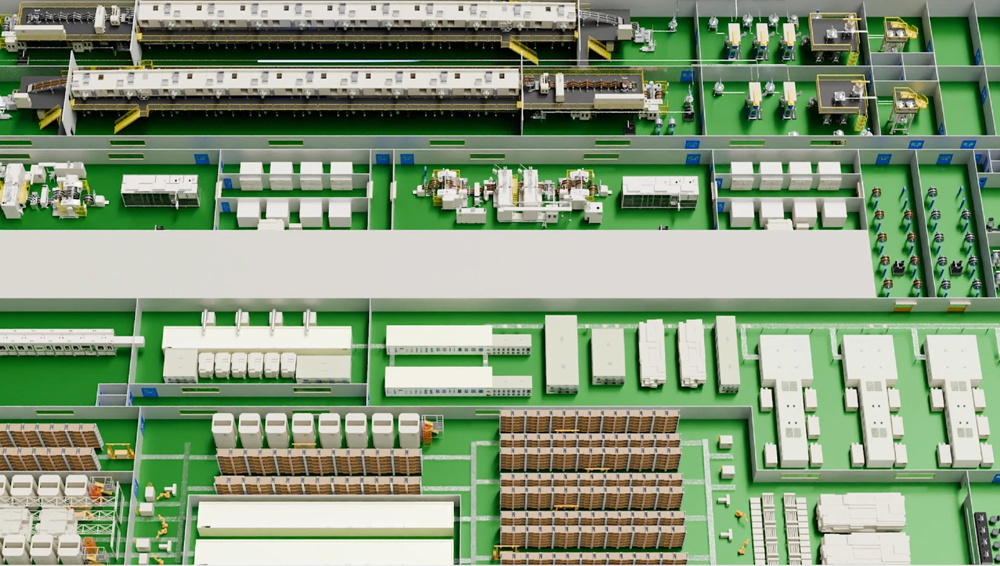
Battery Factory Layout: Optimizing Production Flow
A battery factory layout is not merely a floor plan. It is the physical skeleton that determines whether material moves efficiently between process stations or languishes in unnecessary transport loops. Every meter of electrode roll travel between coating and calendaring, every minute of work-in-progress inventory stranded between formation and grading, and every energy dollar spent maintaining cleanroom conditions in oversized or poorly zoned spaces compounds into a permanent operational cost that no amount of process optimization can fully recover.
The semiconductor industry learned this lesson decades ago. A 2019 study published in the IEEE Transactions on Semiconductor Manufacturing documented that fab layout decisions made during the design phase accounted for up to 30 percent of total operational expenditure variance over a facility’s lifetime. Battery manufacturing, with its comparable cleanroom requirements, multi-step process chains, and sensitivity to contamination, follows the same principle: layout is a one-time capital decision with recurring operational consequences.
Process Flow Mapping: The Foundation of Battery Factory Layout
Every battery factory layout begins with a process flow diagram. The manufacturing sequence for lithium-ion cells—slurry mixing, electrode coating, drying, calendaring, slitting, winding or stacking, electrolyte filling, formation, aging, and end-of-line testing—defines the material movement pattern that the factory must accommodate.
Two fundamental flow geometries dominate battery factory layout planning: the linear flow and the U-shaped flow. Each has distinct advantages depending on production volume, cell format, and site constraints.
Linear flow layouts arrange process stations sequentially along a straight or slightly angled line. Material enters at one end of the facility and exits as finished product at the other. This configuration minimizes cross-traffic and simplifies material handling automation. It is the dominant choice for high-volume cylindrical cell production lines, where the narrow, deep building footprint aligns naturally with the linear process sequence from electrode manufacturing through cell assembly to formation. A representative 2 GWh cylindrical cell line in a linear layout occupies approximately 15,000 to 20,000 square meters, with the electrode manufacturing zone accounting for roughly one-third of the total floor area.
U-shaped layouts bring the material entry and product exit points to the same side of the facility. This geometry reduces the distance that operators and maintenance personnel must travel and simplifies utility connections by concentrating incoming power, gas, and water infrastructure. U-shaped layouts are frequently adopted for pouch cell and prismatic cell production lines, where the assembly processes benefit from closer proximity between quality inspection stations and rework areas. The trade-off is increased complexity in material flow control, as work-in-progress may need to cross active production paths.
Cleanroom and Dry Room Zoning: Contamination Control Through Layout
A battery factory layout must segregate process zones according to their environmental cleanliness requirements. Electrode manufacturing—slurry mixing, coating, and calendaring—typically operates in ISO Class 8 (Class 100,000) or better cleanroom conditions, depending on the cell chemistry and customer specifications. Electrolyte filling and cell sealing require dry room conditions with dew points below minus 40 degrees Celsius and often below minus 60 degrees Celsius for advanced chemistries.
The cost of maintaining these environments scales with the conditioned air volume, making zoning one of the highest-leverage decisions in battery factory layout design. ISO 14644-1 cleanroom standards define particle concentration limits that drive air change rates, filtration requirements, and HVAC energy consumption. A battery factory that places all operations under the most stringent cleanroom classification pays for air handling capacity that most process stations do not need.
Effective zoning follows a cascading cleanliness principle. The most demanding environments—dry rooms for electrolyte filling, ISO Class 7 areas for separator handling—are placed at the core of the facility, surrounded by progressively less stringent zones. Material and personnel flow from cleaner to less-clean areas, never in reverse, to prevent cross-contamination. Airlocks and gowning rooms at each zone boundary serve as physical and procedural barriers. Pressure cascades maintain positive pressure in cleaner zones relative to adjacent less-clean zones, ensuring that air leakage moves outward rather than inward.
Material Handling: AGV, AMR, Conveyor, and Manual Systems
Material movement in a battery factory layout falls into four categories: raw material delivery to process stations, electrode roll transport between manufacturing steps, cell transport through formation and aging, and finished product movement to warehousing. Each category has different weight, fragility, and throughput requirements that dictate the handling technology.
Electrode rolls present the most demanding handling challenge. A finished electrode roll for a large-format pouch cell line may weigh several hundred kilograms and must be transported without surface contact, edge damage, or exposure to ambient humidity. Overhead conveyor systems and automated guided vehicles (AGVs) are the two primary solutions. Overhead conveyors provide dedicated, collision-free transport paths but add structural cost and limit layout reconfigurability—a trade-off that must be evaluated early in battery factory layout planning. AGVs offer routing flexibility at the cost of floor space for navigation lanes and charging stations.
Autonomous mobile robots (AMRs) represent a newer alternative that eliminates the need for fixed guidepaths. AMRs navigate using simultaneous localization and mapping (SLAM) technology and can dynamically route around obstacles. Their adoption in battery manufacturing is growing, particularly in formation and aging areas where cells must be moved between charging cabinets and aging racks at relatively low throughput but with high precision. A 2023 report from Interact Analysis projected that the global market for mobile robots in battery manufacturing would exceed 1.2 billion USD by 2027, driven primarily by gigafactory construction.
Manual material handling, while still present in laboratory and pilot-scale facilities, introduces variability and ergonomic risk that become unacceptable at production scale. The design objective for a production-scale battery factory layout is to eliminate manual transport of electrode materials and finished cells, confining manual operations to quality inspection, maintenance, and process adjustment activities.
Utility Routing: Power, Gas, Water, and Exhaust
The utility infrastructure of a battery factory rivals the process equipment in both capital cost and layout impact. A 2 GWh battery factory layout may consume 10 to 20 megawatts of electrical power, with formation cabinets alone accounting for 40 to 50 percent of total electrical load. Compressed air, nitrogen, process cooling water, and solvent exhaust systems require dedicated piping networks that must be routed through the facility without interfering with material flow paths or cleanroom integrity.
Best practice in battery factory layout places major utility distribution in an interstitial space above the production floor or in a dedicated utility mezzanine. This approach separates utility routing from production operations, simplifies maintenance access, and allows utilities to be modified or expanded without disrupting production. The interstitial space typically adds 2 to 3 meters to the building height, a cost that must be weighed against the operational flexibility it provides.
Solvent recovery systems for NMP (N-Methyl-2-pyrrolidone) used in electrode coating deserve particular attention in layout design. NMP vapor is both a respiratory hazard and a valuable material that can be recovered and reused. The recovery system—typically a condensation and distillation unit—must be located near the coating and drying stations to minimize duct run lengths, but separated from occupied areas by fire-rated construction due to the flammable vapor risk.
Buffer Storage and Work-in-Progress Management
In any battery factory layout, buffer storage zones absorb the throughput mismatch between process stations that operate at different speeds or with different uptime characteristics. A coating line may run at 30 meters per minute while a downstream stacking machine processes electrode sheets at an equivalent rate of 25 meters per minute. Without adequate buffer storage between these stations, the faster machine must either slow down or stop.
The battery factory layout must allocate space for electrode roll buffer storage—an often-underestimated requirement between coating and calendaring, between calendaring and slitting, and between slitting and cell assembly. These buffer zones serve a secondary function as humidity-controlled staging areas where electrode rolls can be held without degradation. The buffer capacity, expressed in hours of downstream consumption, is a design parameter that reflects the expected reliability difference between adjacent process stations.
Formation and aging represent the largest single space commitment in a battery factory. Formation cabinets occupy substantial floor area and generate significant heat that must be removed by facility HVAC systems. Aging racks, where cells rest at controlled temperatures for days or weeks while their electrochemical properties stabilize, consume even more space. A typical 2 GWh factory may have 30 to 40 percent of its total floor area dedicated to formation and aging, and this proportion has remained relatively stable across factory generations because formation and aging times are determined by cell chemistry rather than equipment throughput.
Space Allocation by Process Stage
While every battery factory layout is customized to its specific product and throughput, industry benchmarks provide a useful starting point for space programming. The following allocation represents a typical distribution for a lithium-ion cell production facility:
- Slurry mixing and electrode coating: approximately 15 to 20 percent of production floor area
- Calendering, slitting, and electrode preparation: approximately 10 percent
- Cell assembly (winding or stacking, tab welding, enclosure): approximately 25 to 30 percent
- Electrolyte filling and sealing: approximately 5 percent
- Formation and aging: approximately 30 to 40 percent
- Utilities, buffer storage, and circulation: balance
These proportions shift depending on the cell format. Cylindrical cell lines, with their high-speed winding processes, allocate more space to assembly and less to electrode preparation compared to pouch cell lines with slower stacking processes. Prismatic cell lines fall between the two.
Common Battery Factory Layout Mistakes
Several recurring errors appear across battery factory projects, regardless of scale or geography.
Underestimating formation and aging space requirements is the most frequent. Formation time for lithium-ion cells ranges from 24 to 72 hours depending on the chemistry and protocol, and aging can extend for one to three weeks. Factory planners who allocate floor space based on upstream throughput alone discover after commissioning that the formation and aging area is the bottleneck, with no adjacent space available for expansion.
Treating the dry room as an afterthought is a close second. Dry rooms require specialized HVAC equipment, vapor-sealed construction, and extensive airlock infrastructure. Retrofitting a larger dry room into an existing facility is substantially more expensive than designing adequate dry room capacity from the start. The dry room footprint should be sized for the target production capacity plus a margin for future expansion, typically 20 to 30 percent above the initial requirement.
Neglecting material flow in favor of equipment adjacency leads to convoluted transport paths. Process engineers may prefer to locate related equipment near each other for operator convenience, but this can create material flow patterns that cross, reverse direction, or require double handling. A battery factory layout should be optimized for material flow first, with operator access and equipment adjacency treated as secondary constraints.
Future-Proofing Through Modular Design
A battery factory layout designed for modular expansion accommodates production capacity increases without major rework. The layout determines whether growth is a routine equipment installation or a disruptive reconstruction project. Modular design principles include:
- Leaving expansion space adjacent to each major process zone, not concentrated in a single area
- Designing utility distribution headers with capped branch connections at expansion locations
- Using standardized equipment footprints that allow like-for-like replacement or addition
- Maintaining clear circulation paths that will not be blocked by future equipment installation
The incremental cost of these provisions during initial construction is typically 5 to 10 percent of the total facility cost. The cost of retrofitting a factory that was not designed for expansion can exceed 30 percent of the original construction cost, according to construction industry cost data.
Conclusion
A battery factory layout represents a set of irreversible decisions with compounding financial consequences. The layout determines material handling costs, cleanroom energy consumption, buffer inventory levels, and expansion feasibility for the life of the facility. The layout determines material handling costs, cleanroom energy consumption, buffer inventory levels, and expansion feasibility for the life of the facility. Getting it right requires balancing the competing demands of process flow, contamination control, utility access, and future flexibility.
The most successful battery factory layout designs share a common characteristic: they are designed around the process, not around the building. The building envelope, structural grid, and utility infrastructure serve the production flow, not the reverse. This principle, borrowed from semiconductor fab design and adapted to battery manufacturing, is the foundation of a factory layout that performs efficiently from commissioning through decades of operation.
For battery factory layout design services and turnkey production line solutions covering all major cell formats and chemistries, visit TOBGROUP Solutions or explore our completed projects.


