


Pouch Cell Production Line Equipment List: The Core Answer
If you‘re mapping out a pouch cell production line, here is the non-negotiable equipment backbone: a slurry mixing system, a slot-die or transfer coater, a calender, a die cutter or laser cutter, a Z-stacking or winding unit, an ultrasonic tab welder, a pouch forming and sealing machine, an electrolyte filling system, and formation & grading cabinets. Skimp on any single piece of this chain, and your yield will crater before you even ship a single cell.
-
Mixing precision directly dictates final cell consistency; aim for slurry viscosity control within ±200 mPa·s of the target setpoint.
-
Coating tolerance must hold areal mass loading to < ±1.5% across the full width for 100 Ah-class pouch cells.
-
Dew point in the dry rooms for stacking and filling must stay below -40°C, with excursions under -35°C instantly compromising NMC cathode moisture sensitivity.
-
A fully integrated turnkey line from a single source factory slashes commissioning time by 40–60% compared to mixing vendors.
You know that sinking feeling when your coating line produces beautiful electrodes for 12 hours straight, and then QC drops a stack of rejection reports on your desk the next morning. The cathode weight per unit area drifted. The NMP recovery rate dropped. The cell capacity scatter just doubled. I’ve been in that trailer-sized conference room with a lead production engineer, a furious COO, and a stack of SPC charts that all pointed to one thing: a disconnect between equipment specs and chemical reality. A pouch cell production line is not a grocery list of machines. It is a tightly coupled ecosystem where a 3% error in the mixing stage can murder your formation yields three weeks later. This article breaks down exactly which equipment you need, what tolerances hold, where most lines bleed money, and how to get it right the first time.
The Front End: Electrode Manufacturing Stays the Kingmaker
Before you ever fold a single layer of separator, the electrode process writes the quality DNA of every cell. Get this wrong, and no amount of clever formation protocol can rescue it.
Slurry Mixing: It Starts with Rheology, Not Just Recipes
Most people obsess over the ratio of NMC to conductive carbon. I obsess over the second derivative of viscosity over shear rate. Standard planetary mixers often fail to break the nano-scale agglomerates that kill high-rate performance. That’s why I specify batching with a high-shear dispersion stage and vacuum de-gassing from the start.
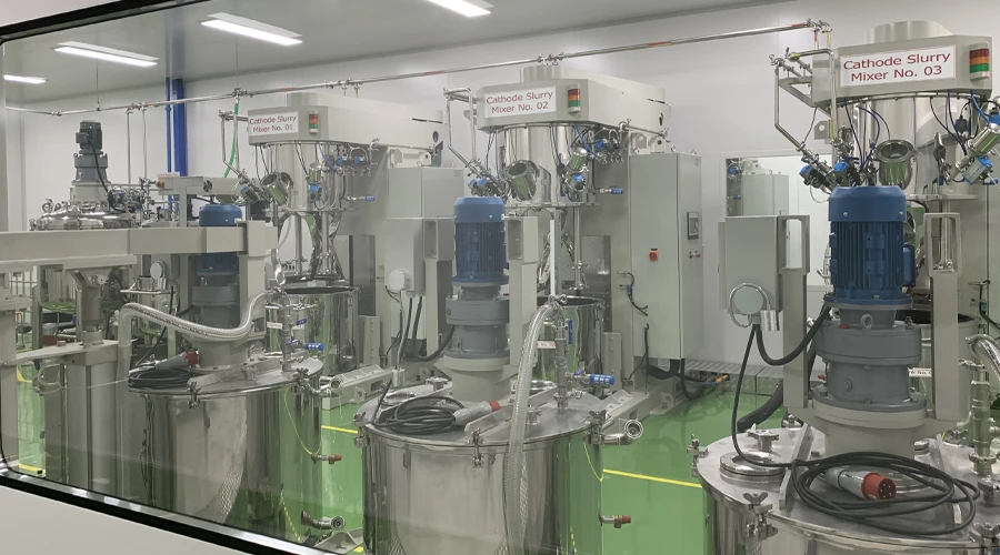
If you trap micro-bubbles in the slurry, you give birth to pinholes during coating. Pinholes become dendrite nucleation sites during charging. That‘s the real failure cascade. In our TOBGROUP turnkey pouch cell line designs, we link the mixer directly to an automatic slurry transfer and storage system that maintains temperature and continuous slow stirring. No more waiting for a drum to move across the hall while the viscosity drifts by 800 mPa·s.
Key spec for a scalable line: Effective mixing volume ≥ 200 L per batch for a 1 GWh annual capacity target, with precise temperature control jacket keeping slurry below 30°C to suppress PVDF gelation.
Slot Die Coating vs. transfer Coating: The A vs. B That Defines Your Pouch Cell Production Line
If you’re serious about electric vehicle-grade pouch cells, this is the fork in the road.
-
Transfer coating (comma-reverse) : Cheaper capital, simpler to operate. But edge elevations rise, and areal mass scatter easily hits ±3%. Acceptable for energy storage systems with lower rate requirements, maybe. For anything that goes into a vehicle, it’s the wrong answer.
-
Slot die coating: The real deal. A closed-system pre-metered fed approach. You control flow rate, pump speed, and gap with micron-level precision. Our TOBGROUP lines employ a patented slot die coating station with integrated beta-ray thickness feedback. This flattens cross-web variation to under ±1.0% — and yes, I’ve verified that with hundreds of off-line weight measurements.
A production manager once told me his coating head dripped dried slurry lumps onto a 60-meter-long wet electrode film. By the time he noticed, they had calendered the whole roll. Three shifts of work went to scrap. The problem? Drying duct velocity turbulence and a poorly tensioned substrate. We fixed it by redesigning the drying nozzle plenum and installing a continuous laser thickness scanner right after the drying ovens. Now the operator sees a heat map of mass loading in real time.
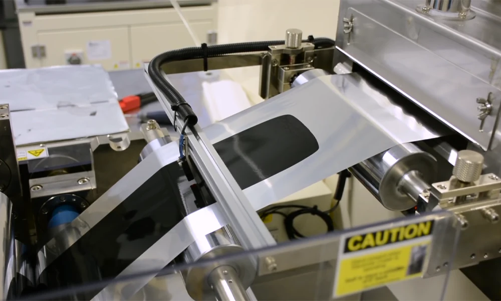
Calendering and Slitting: Crushing Porosity to 25–30%
The cathode comes off the dryer like a chocolate cake — tons of internal porosity. You need a heated calender rolling at 60–90°C to smash that electrode to the target density, typically 3.4–3.8 g/cm³ for NMC811. Too much compaction and you choke the electrolyte pathways. Too little and your volumetric energy density is a joke.
I’ve seen lines where the calender gap drifted by 3 µm over a shift due to thermal expansion of the frame. That’s all it takes to induce a slow migration of binder to the surface. You counter it with closed-loop hydraulic gap control and temperature-stabilized rolls. Then you slit the master roll into daughter rolls. The slitter must leave zero burr on the edge. A 15 µm burr will pierce separator later at a Z-fold corner. Our turnkey module includes a laser slitting option for critical applications, minimizing electrode damage zone to less than 80 µm from the cut edge.
The Heart of Pouch Cell Assembly: Stacking, Tabbing, and Sealing
Z-Stacking Machines: The Productivity Bottleneck
Pouch cells demand folds, not just winding. Z-stacking alternately laminates anode, separator, and cathode sheets into a flat stack. This produces uniform internal pressure distribution and excellent thermal performance. But the mechanical speed limit bites hard.
In older pouch cell production lines, a single vacuum gripper picks and places one sheet at a time, delivering maybe 8–12 PPM (pieces per minute). For a 40-layer cell, that’s a painfully slow cycle. We circumvented this with a multi-zone automated multi-zone Z-stacking machine for pouch cell assembly that runs simultaneous pick-and-place on four table positions, pushing output to 30 PPM without sacrificing alignment ±0.2 mm. If your supplier tells you that you need eight single-head stackers to hit your beat, you’re bleeding capex and floor space. As a pouch cell production line source factory, TOBGROUP integrates the stacking unit directly into a dry-room enclosure with active dew point sensors, eliminating the moisture ingress that silently sabotages your cell life.
Ultrasonic Tab Welding: The 0.15 mm That Makes or Breaks Safety
Here’s a nightmare: a pouch cell passes all formation tests, ships to a pack integrator, and six months later the car throws an isolation fault. Root cause? A cold weld on the aluminum tab that had micro-cracks. During vehicle vibration, the crack propagates.
We use 40 kHz ultrasonic welders with energy and amplitude monitoring for every single weld. The coupon tear test is your mandatory friend. Our turnkey line includes automated weld monitoring that records the weld energy profile, amplitude, and collapse distance for every weld joint. Any deviation outside the control band triggers an eject. It’s non-negotiable industrial ultrasonic tab welding machine for lithium-ion pouch cell manufacturer with integrated quality tracking.
Pouch Forming and Electrolyte Filling: Moisture Kills Here
The aluminum laminate film must be deep-drawn into a pocket without forming micro-cracks in the inner polypropylene layer. If that layer fails, the cell becomes a corrosion time bomb. We incorporate a multi-step cold forming press with precise die clearance control. Right after, the stack gets inserted into the pocket, and the cell enters a side-sealing station before shifting to electrolyte filling.
I insist on a filling process inside a dry room where the humidity is monitored at every cell entry point. We use a high-precision positive displacement pump for filling, which has a repeatability of ±0.3 grams for a 100 Ah cell. Overfill creates wetting issues and lithium plating risks. Underfill starves the stack and creates dead zones. The electrolyte must then soak into the electrode pores under controlled vacuum-pressure cycles. Our system uses a sealed wetting tunnel to do this, cutting wetting time by half compared to atmospheric rest.
Formation, Aging, and the End-of-Line Test Gauntlet
After the cell is sealed, the electrolyte is in place, but the cell is not yet born. Formation — the initial charge-discharge cycle — builds the SEI (solid electrolyte interphase) on the anode. This is a gassing-intensive process, so you need formation equipment with precise pressure and temperature control. We use formation clamps that apply uniform 0.05–0.2 MPa pressure on the cell surface during the first charge. This suppresses gas pocket formation and yields a dense, robust SEI.
After formation, gasses are evacuated in a vacuum sealed chamber, and the cell gets the final seal. Then it goes into aging at 45°C for 7–14 days. Those that drop in OCV (open circuit voltage) beyond 2 mV per day are thrown out. They carry internal micro-shorts. Your end-of-line tester then measures capacity, AC internal resistance, DC internal resistance, and K-value. What many miss: K-value temperature correction. If your aging room swings by 3°C, your K-value data is noise. We integrate a temperature coefficient compensation into our grading software.
Equipment Selection Matrix for a 1 GWh Pouch Cell Production Line
Here’s a no-nonsense comparison that procurement teams find useful. It maps the critical equipment against typical performance must-haves from a turnkey manufacturer perspective.
| Process Step | Core Equipment | Critical Specification | Common Failure Mode If Spec is Missed |
|---|---|---|---|
| Slurry Mixing | Vacuum planetary mixer with high-shear disperser | Viscosity stability ±200 mPa·s, finished slurry filter ≤ 80 µm | Particle agglomerates cause coating streaks and capacity scatter |
| Electrode Coating | Slot die coater + multi-zone flotation dryer | Cross-web areal mass loading deviation < ±1.5% | Edge thick regions produce lithium plating during formation |
| Calendering | Heated calender (2-roll) | Electrode density tolerance ±0.05 g/cm³, no binder migration | High tortuosity limits rate capability and cycle life |
| Slitting/Cutting | Laser slitter or precision mechanical slitter | Burr height < 10 µm, edge damage zone <100 µm | Metal burr pierces separator, leading to micro-short and thermal runaway |
| Stacking | Multi-zone Z-stacking machine | Alignment accuracy ±0.2 mm, single-sheet misplacement detection | Jammed stacks cause internal shorts and scrap entire lots |
| Tab Welding | 40 kHz ultrasonic metal welder | Real-time weld energy and amplitude monitoring, tear test pass | High resistance, hot spots, and eventual open circuit failure |
| Electrolyte Fill | High-precision positive displacement filler | Fill accuracy ±0.5 g, sequential vacuum-pressure cycling | Dry spots accelerate capacity fade by factor of 3 |
| Formation | Pressure-clamp formation system | Channel-level temperature ±0.5°C, pressure uniformity ±5% | Gas pocket delaminates electrode from separator |
This table is your sanity check. When you‘re sourcing a pouch cell production line, ask every potential supplier to demonstrate how their equipment meets these numbers — not in a PowerPoint, but with production data from a line running for at least 72 consecutive hours.
Why a Single Source Factory Changes Your Risk Profile
When you buy a mixing machine from one company, a coater from another, and the stacking unit from a third, you become the systems integrator. Your team ends up debugging communication protocols between PLCs, thermal expansion mismatches between frames, and exhaust duct sizing conflicts that no single vendor accepts responsibility for. I’ve witnessed a 14-month project delay because the coater control electrical cabinet didn‘t have a spare dry contact interface for the calender tension sensor — a trivial oversight that should have been caught during line-level commissioning.
A complete pouch cell production line from a source manufacturer — one that designs and builds core equipment under the same roof — eliminates this integration abyss. TOBGROUP operates as an Original Equipment Manufacturer for mixing, coating, stacking, welding, formation, and full-line automation. The entire line is fully commissioned and debugged at our factory before it ships to your floor. That’s what complete pouch cell production line manufacturer direct source factory means in practice. You don‘t want eight service numbers. You want one engineer who knows the machine that built your cells from slurry to finished cell.
FAQ Section
What is the typical equipment payback period for a 1 GWh pouch cell production line?
At a capacity utilization rate above 70% and selling cells into the e-mobility or premium energy storage market, payback is generally 2.5 to 4 years. The coater and the stacking system represent the largest capital outlays and also the biggest levers for margin improvement.
Can I start with a small pilot pouch cell line and scale later?
Yes, but you must design your pilot line with modular scalability in mind. A 50 MWh pilot that cannot accept a second coating head or an additional stacking gantry will need a complete rebuild when you move to mass production. We recommend a modular platform that uses identical machine architecture from pilot to mass scale.
How critical is the dry room for pouch cells compared to cylindrical cells?
Extremely critical. Pouch cells are far more sensitive to moisture ingress during assembly because the thin aluminum laminate packaging is permeable over long durations and the larger flat surface area absorbs more moisture during manufacturing pauses. Your dry room specification must be tighter by at least 10°C dew point compared to a typical 18650 line.
Do I need laser cutting for pouch cell electrodes?
Not always mechanical, but for high-speed lines making thin electrodes (<80 µm coating) and complex tab shapes, laser slitting offers burr-free edges and lower stress zones. For many mid-speed lines, precision mechanical slitting with carbide blades and active debris extraction is adequate and significantly lower in operating cost.
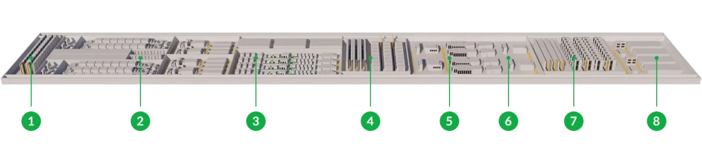
01. Slurry Preparation 02. Electrode Preparation 03. Cells Assembly 04. Electrolyte Filling 05. Formation 06. Degassing 07. Testing 08. Package
Final technical note: If you‘re running a multi-GWh program, don’t just scale the equipment dimensions. The thermal management, roll widths, and drying capacity follow non-linear scaling laws. A 600 mm wide coater doesn‘t simply become a 1200 mm coater by doubling the frame size. Air flotation dynamics, heat transfer rates, and tension control all change. Get that systems-level insight baked into your equipment list from day one, or you’ll be debugging while your competitors ship cells.


