


The fundamental disconnect between academic battery research and industrial commercialization is often summarized in a single metric: Ampere-hours (Ah). For decades, university laboratories have relied on the CR2032 coin cell (typically 0.002 Ah) or small single-layer pouch cells (0.1 to 1 Ah) to validate novel cathode materials, silicon-carbon anodes, and solid-state electrolytes. However, when academic researchers present this coin cell data to automotive OEMs or tier-one cell manufacturers, the response is almost universally identical: “Show us the data in a large-format cell.”
The physics of a 100Ah Electric Vehicle (EV) grade pouch cell are entirely different from a coin cell. The thermal dissipation, the mechanical stress during volumetric expansion, the gas generation during the formation cycle, and the electron distribution across massive current collectors cannot be modeled accurately at the milliampere scale. To cross this “Valley of Death,” top-tier universities are now partnering with one-stop battery solution providers to build their own medium-to-large scale pilot lines.
This case study provides a rigorous engineering blueprint for designing, procuring, and installing a 100Ah Pouch Cell Pilot Line within a university infrastructure. We will examine the critical transition points, from slurry rheology at scale to the extreme demands of multi-layer ultrasonic welding.
Historical Evolution: From Manual Casting to Automated Precision
To understand where we are going in 2026, we must understand the trajectory of coating technology. Early battery research relied on “Tape Casting,” a process borrowed from the ceramics industry. The Doctor Blade was the natural evolution of this-a simple, rigid bar that leveled a pool of slurry. It worked well for the early LCO (Lithium Cobalt Oxide) batteries where energy density requirements were modest.
However, as the industry moved toward high-power and high-capacity cells, the limitations of “self-metered” systems became apparent. The introduction of Slot Die coating, a technology refined in the photographic film and high-end paper industries, revolutionized the battery manufacturing facility. It moved the industry from a “passive” process, where the foil dragged the fluid, to an “active” process, where the equipment dictates the fluid’s behavior. At TOBGROUP, we have documented that this shift alone can improve cell-to-cell consistency by over 40% in a pilot line environment.
I. Facility Infrastructure: The Prerequisite for High-Capacity Cells
Before a single piece of battery manufacturing equipment is ordered, the university must address the facility. A 100Ah cell contains a massive volume of highly reactive materials. The infrastructure is not merely a housing requirement; it is an active variable in the cell’s electrochemical performance.
1. The Ultra-Dry Room Engineering
The most expensive and critical infrastructure for a battery pilot line is the Dry Room. In a coin cell lab, an argon-filled glove box is sufficient. For a 100Ah pouch cell line involving roll-to-roll coating, automated stacking, and liquid electrolyte filling, a walk-in dry room is mandatory.
For standard Lithium-ion chemistries (NMC/Graphite), the dry room must maintain a dew point of -40 degrees Celsius (approximately 127 ppm of water). However, if the university intends to research next-generation Sulfide Solid-State Electrolytes or Lithium-Metal anodes, the requirement drops to -60 degrees Celsius (less than 10 ppm). Achieving this requires massive Rotary Desiccant Dehumidifiers. The HVAC engineering must account for the latent heat generated by the heated vacuum drying ovens and the moisture emitted by the researchers themselves (typically 100 to 150 grams of water per person, per hour).
2. Floor Loading and Vibration Isolation
University buildings, particularly older science blocks, are often not rated for industrial floor loading. A roll-to-roll slot die coater combined with a high-pressure continuous calendering machine can weigh several tons and exert immense point-loads. Furthermore, calendering machines and planetary mixers generate low-frequency vibrations that can interfere with adjacent high-resolution electron microscopes (TEM/SEM). At TOBGROUP, our facility planning team works with university architects to design custom vibration-isolation pads and calculate dynamic floor stress before equipment delivery.
3. NMP Solvent Recovery and Exhaust Management
The coating process utilizes N-Methyl-2-pyrrolidone (NMP) as the solvent for the cathode slurry. NMP is toxic and strictly regulated by environmental health and safety (EHS) standards. A 100Ah pilot line requires an integrated NMP Recovery System attached to the coater’s exhaust. This system utilizes chilled water condensation or zeolite rotor adsorption to capture the NMP vapor before it reaches the university’s central exhaust, ensuring compliance with local environmental laws.
II. Front-End Processing: Scaling the Slurry and Electrode
To produce a single 100Ah pouch cell, you require approximately 3 to 4 square meters of double-sided coated electrode. A standard batch of 10 cells requires 40 square meters. You can no longer mix in a beaker or coat with a handheld blade.
1. High-Shear Mixing at the 50-Liter Scale
The transition from a 1-liter lab mixer to a 50-liter dual planetary vacuum mixer alters the fluid dynamics fundamentally. In large batches, temperature control becomes the primary challenge. High shear forces generate intense localized heat, which can cause the PVDF binder to crystallize or the solvent to evaporate prematurely.
The 50L mixers we supply for university pilot lines are equipped with dual-layer water cooling jackets and multi-point PT100 temperature sensors. Furthermore, vacuum degassing during the final mixing stage is critical. Any micro-bubbles trapped in a 50-liter batch will translate into pinholes during the coating process, causing catastrophic lithium dendrite growth in a 100Ah cell.
2. Coating and Calendering for Energy Density
As discussed in our previous analysis of slot die technology, pre-metered coating is non-negotiable at this scale. For 100Ah cells, the areal mass loading is pushed to its limits (often exceeding 20 milligrams per square centimeter for high-energy applications).
Once coated and dried, the electrode must be densified using a hydraulic roll press. Calendering a 300mm wide electrode requires hundreds of tons of linear pressure. If the pressure is not completely uniform across the rollers, the foil will wrinkle or “camber.” We equip our pilot calendering machines with “Roll Bending” technology and induction heating to soften the binder, allowing for high compaction density (e.g., 3.6 g/cm3 for NMC cathodes) without crushing the active material particles.
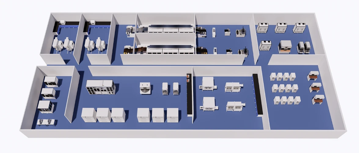
III. Middle-End Processing: The Architecture of the Pouch
The assembly of a pouch cell is an exercise in extreme mechanical precision. A 100Ah cell is not a single electrochemical unit; it is a parallel connection of up to 80 or 100 individual layers of cathode, separator, and anode.
1. Z-Stacking vs. Winding
While cylindrical cells use winding, large-format pouch cells rely heavily on Z-Stacking. In a Z-stacking machine, a continuous strip of separator is folded back and forth in a “Z” pattern, with discrete sheets of cut cathode and anode inserted into the folds.
The engineering tolerance here is unforgiving. The anode must be slightly larger than the cathode (the “Overhang”) to prevent lithium plating at the edges during fast charging. If the stacking mechanism misaligns a single cathode sheet by 0.5 millimeters so that it extends past the anode, the entire 100Ah cell is a fire hazard. Our advanced pilot stacking machines utilize multiple CCD camera vision systems to perform closed-loop alignment correction on the fly, ensuring perfect overhang geometry for every layer.
2. The Physics of Multi-Layer Ultrasonic Welding
Once the cell is stacked, all 80 layers of aluminum foil (from the cathodes) must be welded to an aluminum tab, and all 80 layers of copper foil (from the anodes) must be welded to a nickel or copper tab.
This cannot be done with laser welding because the thin foils would simply vaporize. Instead, we use ultrasonic welding equipment. This process uses high-frequency acoustic vibrations (typically 20 kHz to 40 kHz) applied under pressure to create a solid-state weld.
Welding 80 layers for a 100Ah cell requires massive power-often 3000 to 4500 Watts. The challenge is “weld penetration.” If the energy is too low, the bottom layers will not bond (causing high internal resistance). If the energy is too high, the sonotrode (the vibrating tool) will tear through the top layers. At TOBGROUP, we provide customized sonotrode horn designs and dynamic pressure control systems specifically engineered for the heavy tab-to-foil ratios found in EV-grade cells.
3. Pouch Forming and Deep Drawing
The casing of a pouch cell is made of Aluminum Laminated Film (ALF)-a composite of nylon, aluminum foil, and polypropylene. To hold the massive 100Ah stack, a deep “cup” must be cold-formed into the ALF using a pouch forming machine.
For high-capacity cells, the depth of this cup can exceed 10 millimeters. During deep drawing, the ALF experiences extreme tensile stress. If the punch and die are not perfectly polished, or if the clamping pressure is incorrect, the aluminum layer within the film will micro-fracture. These invisible fractures will allow moisture to enter the cell over its lifespan, leading to catastrophic swelling. Our pilot-scale forming machines utilize servo-driven punches with programmable speed curves to gently stretch the film without violating its yield strength.
IV. Back-End Processing: The Chemistry of Activation
Once the stack is sealed inside three sides of the pouch, the process transitions from mechanical engineering back to chemical engineering.
1. Vacuum Electrolyte Filling and Wetting Dynamics
Injecting electrolyte into a CR2032 coin cell takes seconds. Injecting 100 to 150 grams of electrolyte into a tightly compressed 100Ah pouch cell stack is a massive hydrodynamic challenge. The porosity of the compressed electrodes and the nanopores of the separator create immense capillary resistance.
If you simply pour the fluid in, it will pool at the top, leaving the center of the cell completely dry. When the cell is charged, these dry spots will become dead zones, forcing the wet areas to operate at double their designed C-rate, destroying the cell immediately.
In our battery pilot lines, we implement vacuum electrolyte filling systems. The unsealed pouch is placed in a chamber, and a deep vacuum is drawn, removing all air from within the electrode pores. The electrolyte is then injected. When atmospheric pressure is reintroduced, it physically forces the liquid deep into the center of the stack. For 100Ah cells, this vacuum-pressure cycle must be repeated multiple times, followed by a high-temperature aging rest period to ensure total homogeneity of wetting.
2. Formation, Gas Generation, and Secondary Sealing
The final manufacturing step is “Formation”-the first careful charging of the battery to create the Solid Electrolyte Interphase (SEI) layer on the anode.
During the SEI formation in a liquid electrolyte system, a significant amount of gas (primarily ethylene, hydrogen, and carbon monoxide) is generated. In a 100Ah cell, this gas volume is massive. This is why pouch cells are designed with a “Gas Bag”-an extra, unsealed length of the ALF pouch where the gas can collect.
After formation is complete on our high-precision battery testing channels, the cell is transferred to a vacuum final sealing machine. This machine pierces the gas bag in a vacuum environment, extracts all the accumulated gas, and applies a final thermal seal directly above the cell body. The excess gas bag is then cut off and discarded. This process requires extreme precision to ensure no electrolyte is sucked out along with the gas, which would alter the cell’s carefully calculated fluid-to-capacity ratio.
V. Quality Control and Safety in a University Setting
An industrial Gigafactory has dedicated safety bunkers for cell testing. A university laboratory is often located in a building filled with students and other research departments. Therefore, the Quality Control (QC) and Safety protocols for a 100Ah line must be flawless.
1. Non-Destructive Testing
Before a 100Ah cell is ever charged, it must be inspected. We integrate high-voltage Hi-Pot testing machines to detect micro-shorts before electrolyte filling. More importantly, we recommend X-Ray inspection systems to verify the internal alignment of the Z-stack. If an anode overhang anomaly is detected via X-ray, the cell is scrapped before it becomes a thermal runaway risk.
2. Thermal Management and EHS Protocols
During the cycle-life testing of a 100Ah cell, a thermal runaway event releases an incredible amount of energy, toxic hydrofluoric acid (HF) gas, and fire. The battery testing equipment provided for university pilot lines must be housed in explosion-proof environmental chambers equipped with active fire suppression systems and dedicated rapid-exhaust ventilation.
VI. Economic Blueprint: Building the 100Ah Pouch Cell Pilot Line
To provide university Principal Investigators (PIs) and department heads with a realistic framework for grant applications, here is a conceptual parameter layout for a standard 100Ah NMC/Graphite pilot line engineered by TOBGROUP:
| Production Stage | Key Equipment Selection | Engineering Purpose for 100Ah Scale |
| Material Mixing | 50L Vacuum Planetary Mixer | Handles high-viscosity slurries with thermal cooling jackets to prevent binder degradation. |
| Electrode Coating | Continuous Slot Die Coater | 3-zone convection oven; pre-metered precision for high areal mass loading >20mg/cm2. |
| Roll Pressing | Hydraulic Hot Calendering Machine | Induction heating to achieve >3.5 g/cm3 compaction density without foil wrinkling. |
| Electrode Cutting | Laser Slitting & Punching Machine | Burr-free cutting of massive electrode sheets to prevent internal short circuits. |
| Cell Assembly | Fully Automated Z-Stacking Machine | Vision-guided alignment to ensure perfect anode-to-cathode overhang across 80+ layers. |
| Tab Welding | 3000W+ Ultrasonic Welder | High-energy penetration for welding 80 layers of foil to 0.2mm thick terminal tabs. |
| Pouch Packaging | Deep-Draw Pouch Forming Machine | Controlled tension drawing to form 10mm+ deep cavities in ALF without micro-fracturing. |
| Electrolyte Process | Vacuum Filling & Degassing Chamber | Multi-stage vacuum pressure cycling to force electrolyte into the center of the dense stack. |
| Formation & Testing | 5V 100A Regenerative Test Channels | Energy recovery systems to manage the massive electricity consumption of forming 100Ah cells. |
VII. Conclusion: The Hub of Next-Generation Innovation
Building a 100Ah pouch cell pilot line within a university is a monumental undertaking. It transforms a chemistry department into a true advanced manufacturing hub. It allows researchers to prove that their novel materials can withstand the physical compression of calendering, the thermal stress of high-shear mixing, and the complex fluid dynamics of vacuum wetting.
When a university can present cycle-life data generated from a perfect, internally manufactured 100Ah pouch cell, they are no longer just publishing papers-they are dictating the future of the automotive supply chain.
At TOBGROUP, we understand that academic researchers are not necessarily mechanical engineers. That is why our approach to university battery laboratories is holistic. We do not drop pallets of equipment at the loading dock; we design the facility, integrate the machines, train the post-doctoral students on industrial operation protocols, and provide the ongoing material supply necessary to keep the pilot line running. We build the bridge across the Valley of Death, allowing your innovations to reach the commercial world.
About TOBGROUP
TOBGROUP is a globally recognized one-stop solution provider for the battery industry, dedicated to accelerating the commercialization of advanced energy storage technologies. Our expertise encompasses the entire battery lifecycle, providing comprehensive solutions for battery laboratory research, pilot-scale production lines, and fully automated mass manufacturing facilities. We cater to all dominant and emerging chemistries, including Lithium-ion, Solid-State, Sodium-ion, and Lithium-sulfur systems.
By combining cutting-edge customized battery equipment, rigorously tested battery materials, and unparalleled technical consultancy, TOBGROUP empowers universities, research institutes, and global cell manufacturers to transition seamlessly from conceptual electrochemistry to market-leading products. We are your dedicated engineering partner in the pursuit of the ultimate battery.


